Robotics Studio
Below is the full journey video, I hope you enjoy!
(click the bottom right corner for music)

Youtube link to the video:
https://www.youtube.com/watch?v=qdeh2odfarg
We initially created concept sketches, considering the weight of the PLA, and the weight of the hardware (i.e the battery, the DC converter, the raspberry pi and the microcontroller). These sketches allowed us to realize the space that the robot occupies, as well as survey an array of design considerations that put the least torque on the motors while still allowing for a functional robot.
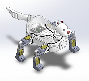
We then designed this in CAD (SOLIDWORKS). The initial realistic photo renderings of our robot demonstrated that our robot had an extremely high center of mass. This resulted in the robot resting in an unstable equilibrium, and therefore forced us to iterate our design from a bipedal robot to a four legged robot. We inputted the materials into our model to get the total mass and used this in conjunction with the center of mass to find the torque on the motors.
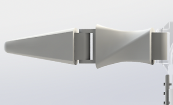
Now that we have narrowed the design considerations down and developed the body and places for the hardware, we determined that it was time for us to choose the optimal mechanism for the leg. This resulted in the choice of a series leg with parallel bars. This leg design allowed the lower portion of the leg to remain adjacent to the ground. Therefore, we did not need to make an ankle joint, and were able avoid placing too much stress on a motor at this joint. The tail was designed to swing freely, and was mostly decorative. As a result, we determined that we should do a topology optimization on it so it has the lowest moment of inertia possible while still being large enough to resemble a real dog tail.
We designed this in SOLIDWORKS, and determined that we wanted to have the most modularity possible for this robot. Therefore, when a part breaks, we can isolate the issue and have a simple fix. All of the parts were 3D printed and sliced using a software called Cura. This allowed us to choose the infill patterns that allowed us to use the least material while also having isotropy
The next stage of bringing this robot to life is assembling the legs. Once this is done, we can control the servo motors with a python package to do a motion study on the legs to find the extreme leg positions possible for this robot. This is done with a battery, soldered into a step down DC converter that is connected to our micro processor. This micro processor connects our computer to our motors, as well as gives our motors power from the DC converter.
Concept Sketches


First Iteration


Second Iteration


Animation of Exploded View
Motion Study of Leg


The next step was to assemble the robot. Doing this, we needed to reprint many of the parts to iterate for many design problems that we were confronted with. Along with drilling, cutting, soldering and even sanding, we also completed all of the wiring between the hardware and the motors to make this robot fully functional. The assembly of the lower half, the non decorative portion, is seen in the image below.


Once the functional portion of the robot is assembled, we downloaded the latest version of python, as well as the LX-16A library. We set up a headless connection on our raspberry pi by allowing ssh. and remote logging into it. Therefore the robot is run wireless off of a battery and wifi. With the headless connection we were able to test out different code and motion studies on the robot. Some of the motions can be seen below.
Here we demonstrate the fluidity of motion that the robot is capable of by placing legs on opposite sides of the body out of phase. Next, we demonstrate the auto homing mechanism that we developed. This mechanism can be called on at any time and can force the robot to stand with each of its ankles straight and each knee bent at 90 degrees.
Finally, we combined a dance move the auto homing in a script. This demonstrated how the robot can find its home position from any arbitrary angle. This can be seen in the video to the right. Here the robot starts by dancing, then ends at a random point in the dance, and auto homes itself.


Key Framing Code
Walking Code

Auto Homing Code

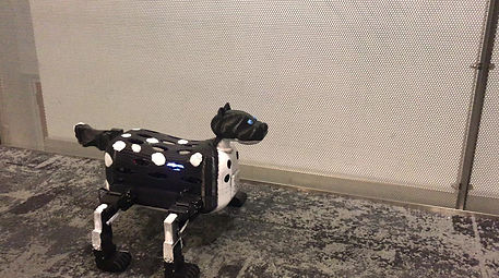
Now that we have our robot fully printed and the shell and decorative parts assembled on the robot (as you can see on the left), it is time to program some boot up, test, and power down routines into the robot.
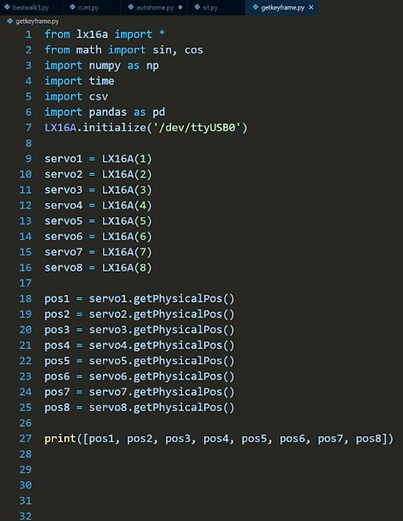
These routines use a combination of key framing techniques, and inverse kinematics. The key framing technique is an iterative coding process, where we shut all of the motors off with one of our programs, then move all of the links and appendages to their desired position, then run one of our programs that gets the location of all of the limbs based on the current angle of the motors. We then shut the motors off and run the code to get the new desired position of the motors. Finally, we interpolate between these positions and do so using sin or cos wave so we can gently accelerate and decelerate the motors to avoid burning out the motors from applying too much torque to them.
The code on the left is what we use to get the key frames. This just prints the current positions of the motors so we can move between them
Next we have a code that is designed to make our robot walk forward. This puts the front right leg and back left leg in sync and perfectly out of phase with the front left and back right legs. This allows the robot to remain at a stable equilibrium while also move forward. Because the battery can only support 24V and each of the 8 motors need 6V, we had to run a for loop and pulse the power from the back legs to the front legs very quickly, so the motion is still fluid to the viewer, however the motors do not use all of the battery's voltage at once. The last thing to note about this code is that all of the motion is done with sinusoids to be able to decelerate each joint before it changes direction. These angles were all determined with inverse kinematics, and the robot walks at a measured 4.4 cm/sec.
Finally we have our auto homing code ensures that all of the motors are at their middle position. This is the position that all of the hips are at 90 degrees and all of the feet are flat on the floor.
Below are videos of the robot, sitting and then standing up again (boot down and boot up routines), the robot walking and finally the robot dancing.
Robot Walking
Robot Shutting Down and Starting Up (sitting and standing)

The next video is a video of the robot going through a sequence of moves in series, including a bonus video of the robot doing pushups to stay in shape. This dance montage concludes with the robot shutting/sitting down and then starting/standing up again.
