Laser Shock Peening Research and Simulation

A PDF to the full paper is available by clicking the PDF button to the right
The objective of this research was to replicate (with a Finite Element Analysis software: Abaqus), and analyze Laser Shock Peening (LSP). LSP is a process that enhances the mechanical properties of a metal sample, and is generally applied after the machining process. One of the most advantageous outcomes of LSP is the compressive residual stress (CRS) that is used to enhance the fatigue life of an object, as well as, hamper crack propagation. This research used Abaqus, along with an extensive understanding of the intricacies of LSP, to accurately model LSP and ultimately explore the compressive residual stress imparted on a substrate. This was done to determine the optimal overlap percentage to use in the LSP process.
As you can see on the image of the mesh to the right, we placed a bias on the mesh to get the best resolution on the surface (where the most residual stress is harbored). We employ two different types of boundary conditions. The first that we use is a displacement/rotation boundary condition. We apply this to specific sides of the substrate to replicate how the sample will be fixed in a real LSP experiment. The second
For this simulation, we modeled our laser to have a gaussian profile for pressure, with respect to distance. The top line (blue line) represents the laser at maximum intensity, and the lower line (orange line) represents the laser at half intensity. With less intensity we get less variation from the center of the shock. This was all written into a subroutine that was written in FORTRAN and performed in Abaqus.
LSP is purely a mechanical process. The components of the apparatus that are necessary to efficiently apply LSP to a surface are as follows: a clear overlay, an opaque overlay (ablative layer), a laser, and a substrate to work on. The process begins by directing a pulsed laser beam through the clear overlay, and into the opaque overlay that lays on the top of the surface of the sample. This results in the opaque overlay vaporizing and producing a plasma that adiabatically expands and imparts a sudden pressure on the surface of the sample/substrate. This surface pressure results in a shock wave that emanates through the material, and if the stress of the shock wave exceeds a certain threshold (the Hugoniot Elastic Limit), we get plastic deformation.
Our results from the simulation are below.
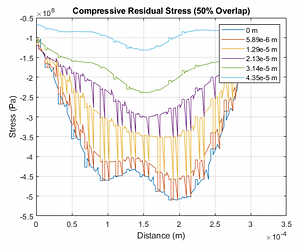
We were able to extract the data from these simulations and create graphs that demonstrate the stress as it varies across the surface of the substrate (like the graph on the right. This is significant because most of the crack propagation occurs on the surface, so a larges CRS on the surface hampers crack growth and fatigue life the most.
We were also able to develop graphs that measure the CRS as we vary in the Z direction, or into the depth of the substrate (as shown on the right). This demonstrates the depth of the LSP which is important for larger stress loadings.
These graphs allowed us to extract even more data and consolidate it into tables to allow us to observe overarching quantitative trends to help us determine the best overlap. These tables can be seen below.


The Figure above represents an overlay of stress vs time and strain vs time at the center on the same graph. The orange represents strain and the green represents stress.

Images of Stresses at Varying Overlaps (Top Left is 0%, Top Right is 25%, Middle Left is 50%, Middle Right is 75%, and Bottom Left is 100%)

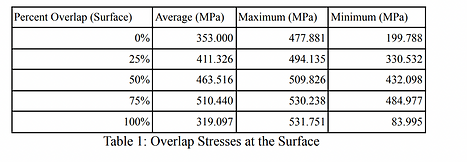


From these tables, we see that we take into account the distribution of and average stress at the surface, the stress under the surface, as well as the energy usage, the 50% over lap is the ideal percent overlap. It uses significantly less energy than the 0% and 25% overlap, while providing more average CRS under the surface of the substrate, while producing a competitive surface CRS to the 75% and 100% overlap simulations.
To conclude, we look to the future of LSP, more specifically hybrid manufacturing. We do this to consider the potential for platforms that allows the machining process and the LSP process to work concurrently to achieve a synergistic effect. Through analysis of the anisotropy and grain boundaries, we discuss how the hybrid manufacturing process with LSP, otherwise known as 3D LSP, impacts the material properties.