Complex Linkage Mechanism to Press Arcade Buttons in Sequence

For this project, I am currently working in a team to design, build, and control a complex linkage mechanism to press arcade buttons in sequence as quickly as possible. We are responsible for kinematic planning, the creation of a detailed 3D model, the manufacturing of linkage components (milling, laser cutting, water jet cutting and 3D printing), the wiring, the sensor usage, the signal processing, the transmission design, the control system tuning, and the actuation.
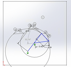
For the linkage mechanism, we designed the apparatus to have a short input linkage that keeps the transmission angle (the angle between the coupler and the output linkage) between 30 and 150 degrees. We optimized this by determining an apparatus that can reach all three couplings of buttons in their desired orientation with a transmission angle between 52 and 137 degrees to get as much torque from the motor to the linkage as possible. The images on the right demonstrate a 1 dimensional representation of the linkage reaching each of the three button positions.
The small circles represent the buttons, the large circles represent the trajectory of the button pressing mechanism, and the trapezoidal feature represents out coupler.
Our coupler mechanism was designed to have the lowest moment of inertia while still having the strength to carry the solenoid that we are using to move the acrylic that ultimately presses the button. This will be attached to the input and output links with bearings that let the coupler rotate with minimal friction.
Position 1

Position 2

Position 3

The programming will be done with an Arduino, and we will have a limit switch providing the Arduino with a pulse of voltage, telling it when it has reached an extreme point. This is how we will know the position of one of our buttons. Next we will use an encoder that is put on the transmission that we design to determine its position relative to the first buttons. This will help us locate the other buttons. When we reach the location of the sought after button, we will program the motor to slow down using a sinusoidal wave to represent the velocity. Once the linkage is stopped, the solenoid will be commanded to move the acrylic that presses the button.


The transmission angle that we devise will use inertia matching and will take into account the moment of inertia of the linkage from the ground pivot of the input link. With this we can optimize our torque. We got the moment of inertia of each link and using the parallel axis theorem we were able to get the moment of inertia of the entire linkage. Once we have this, we use the equation below to get our gear ratio.


The image above displays an excel file that we used that has the equation on the left ingrained into it. Therefore, we were able to input our data into this file and have the transmission ratio generate automatically. We used our Solidworks assembly with the materials input into it to find the measurements, masses and the center of mass. The images below is what our final design looks like. We got a value of 1.82 for our transmission ratio, however this does not account for the added moment of inertia of the solenoid. We also want to select a conservative transmission ratio so the encoder on the motor has a better resolution. Therefore, we selected a ratio of 2.5.


Once we completed the designing process, it was time to machine and assemble this mechanism. We began by saving our links and baseplate as a dxf file so we could input the file into the water-jet cutter, however because we need to press-fit the bearings into the links and baseplate, we needed to make the holes smaller than we want. We only made pilot holes with the water jet because of the kerf of the water jet cuts. Therefore, we used a Computer Numerical Control (CNC) milling machine to drill and ream the remainder of the holes. Next we used a lathe to cut the remainder of the hard stops and spacers. Once we had all of the parts machined, we assembled the mechanism, resulting in the images below.


